|
|

|
 (*)
ASTM :E-2157-01 (*)
ASTM :E-2157-01 |
| |
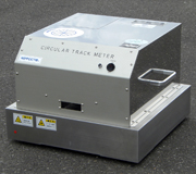
 The
C.T. Meter (Circular Track Meter) is a road surface macrotexture
profiler, in which a CCD (Charged Coupled Device) Laser Displacement
Sensor is used. It is designed to measure on the same circular
track on which the D.F. Tester measures
the dynamic coefficient of friction. There are various methods
to characterize road surface macrotexture profiles. The C.T.
Meter reports the MPD (Mean Profile Depth) and the RMS (Root
Mean Square). The IFI (International Friction Index) can be
computed using the C.T. Meter in combination with the D.F.
Tester. The
C.T. Meter (Circular Track Meter) is a road surface macrotexture
profiler, in which a CCD (Charged Coupled Device) Laser Displacement
Sensor is used. It is designed to measure on the same circular
track on which the D.F. Tester measures
the dynamic coefficient of friction. There are various methods
to characterize road surface macrotexture profiles. The C.T.
Meter reports the MPD (Mean Profile Depth) and the RMS (Root
Mean Square). The IFI (International Friction Index) can be
computed using the C.T. Meter in combination with the D.F.
Tester.
(*) There are also several
documents by which that's transcribed as Circular Texture
Meter.
This instrument is also contained
in the FHWA's (Federal Highway Administration) Measuring
Instrument Guide.
|
| |
| |
U.S.
Patent : |
US 6,679,106 B1 |
| |
European
Patents : |
No.EP1203928
<Designated States>
England , France , German , Italy ,
The Netherlands |
| |
Japanese
TradeMark : |
NIPPOCTRM |
|
|
 |
 |
 |
| FRONT VIEW |
BACK SIDE |
|
 |
| |
| 1. |
Displacement Sensor
: CCD Laser Displacement Sensor |
| 2. |
Measuring Range of
the Laser : 30 mm (65 - 95) |
| 3. |
Laser Beam Spot Size
: ø70 µm |
| 4. |
Wave Length : 670
mm |
| 5. |
Vertical Resolution
: 3 µm |
| 6. |
Measuring Radius
: 142 mm |
| 7. |
Number of Samples
: 1,024 per revolution |
| 8. |
Sample Spacing :
0.87 mm (± 0.05 mm) |
| 9. |
Divides one rotation
into 8 segments and computes the MPD and/or RMS of each
segment. |
| 10. |
Number of Samples
per segment : 128 |
| 11. |
Tangential velocity
: 6 m/min. |
|

|
| |
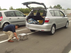
| 1. |
Small (approx. 13 kgs.)
and Portable |
| 2. |
Short time for a measurement
(approx. 45 seconds) |
| 3. |
Reports MPD and RMS with
good reproducibility |
| 4. |
Easy measurement without
operator influence |
| 5. |
An automobile battery (12V
DC , 24W) is used for power supply |
| 6. |
Four directions of data
can be obtained in one measurement, i.e., driving direction,
perpendicular to the direction of travel, 45° to the
direction of the travel, and the whole circumference.
|
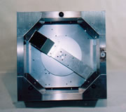
The number of samples per one
rotation is 1,024 (892 mm) which is divided into 8 segments
for the computation of each MPD and/or RMS.
Analysis of the individual segments can be performed to examine
the profile parallel to the
direction of travel (Segments A and E) and perpendicular to
the direction of travel (Segments C and G). The average of
B,F and D,H indicates MPD for 45° to the direction of
travel.
The overall MPD can also be obtained as an average of the
A through H segments.
|
 |
| |
The displacement sensor for this
instrument is a CCD which is mounted on an arm that rotates
at 80 mm above the surface in a circumference of 142 mm radius.
The arm is driven by a D.C. Motor at a tangential velocity
of 6 m/min. The CCD is sampled 1,024 times per revolution
providing a sample spacing of 0.87 mm by an A/D converter.
The data are recorded in memory in a notebook computer. The
data are segmented into eight 111.5 mm arcs of 128 samples
each. The computer software computes the MPD and/or the RMS
of each segment. Optionally the MPD and RMS can be computed
for the middle 100 mm of each segment.
Schematics
of the measuring system
|
 |
|
|
Sidewalks,
pavements, floor surfaces of buildings, sports facility floors,
etc. |
 |
| |
C. T. Meter :
400mm (W) x 400mm (L) x 270mm (H)
13 kgs.
With Carrying Case :
470mm (W) x 590mm (L) x 330mm (H)
24 kgs.
|
 |
| |
|
|
|